7.2 Installing and connecting the sensors
Install the sensors and connect them to the heat pump controller before starting the heat pump. The controller is in the control unit behind the cover plate. The sensors are in the manual folder of the delivery and they are marked by the position.
Install the outdoor temperature sensor in a shaded location on a wall facing north or north-east. Do not install the sensor near a window or door.
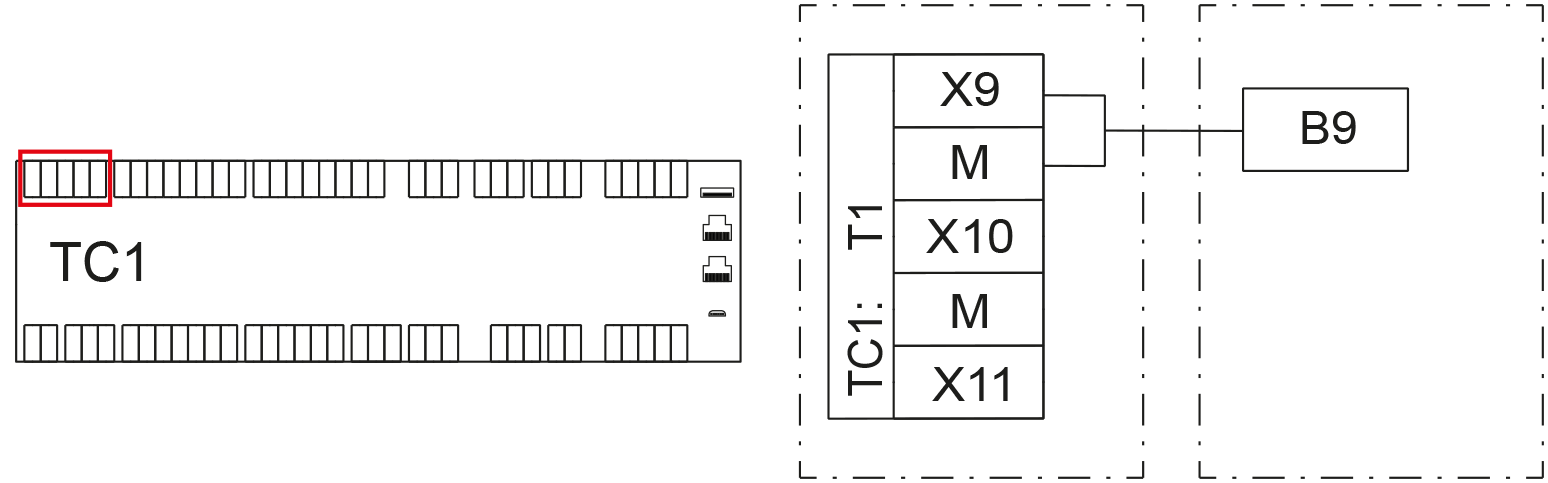
Connect the outdoor temperature sensor (B9) to the connectors X9 and M of the controller TC1.
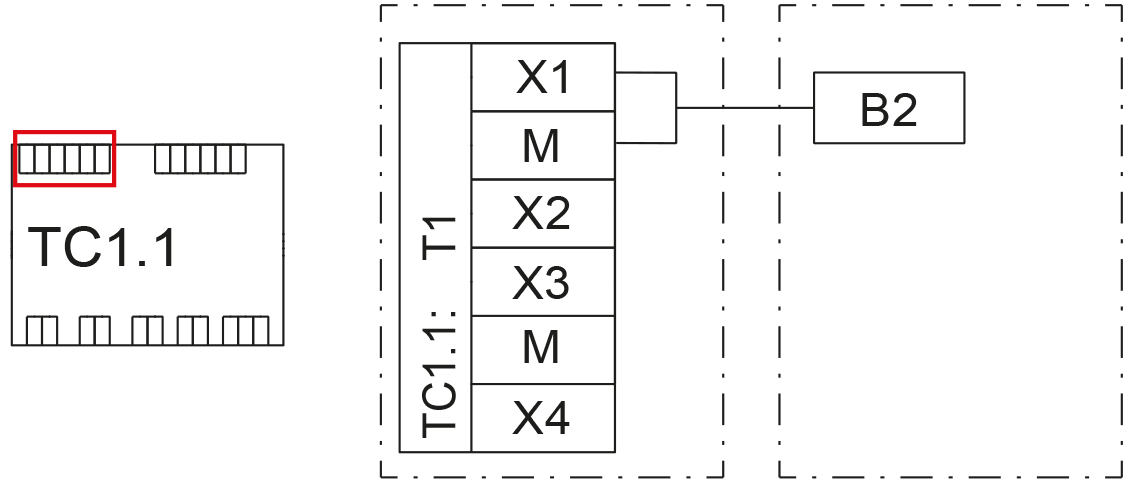
Install the upper sensor of the domestic water accumulator (B2) in the sensor pocket at the top section of the accumulator.
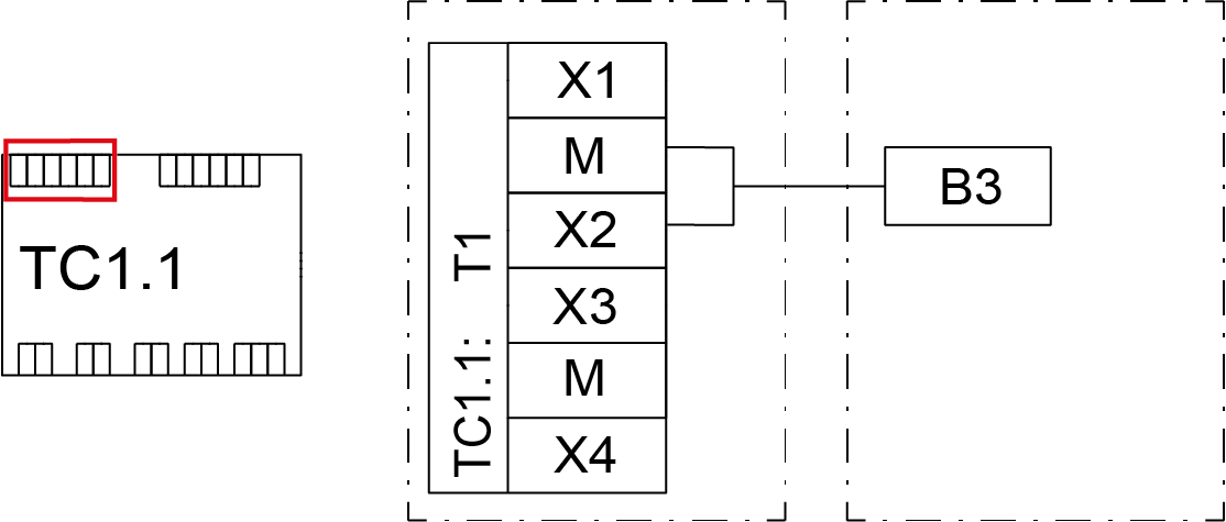
Install the lower sensor of the domestic water accumulator (B3) in the sensor pocket at the middle or bottom section (1/3 from below) of the accumulator.
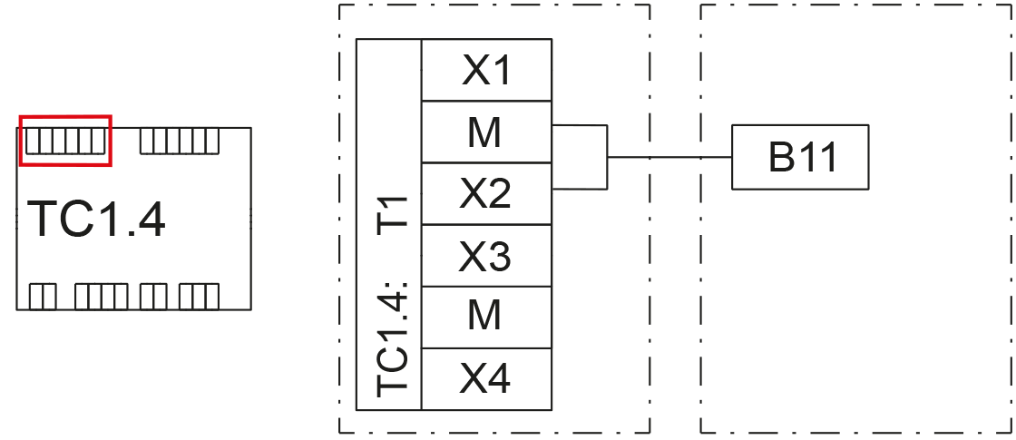
The common flow sensor (B11) is installed in systems that involve accumulator resistors or an external additional heat source (such as oil, gas, district heating or electric boiler). The sensor acts as a sensor for controlling additional heat.
Install the sensor in the common supply pipe of the heating system after the additional heat source. The sensor is an 80 mm water sensor that does not require a separate sensor pocket. The sensor has a 4 m cable with connector. You can extend the sensor in the junction box.
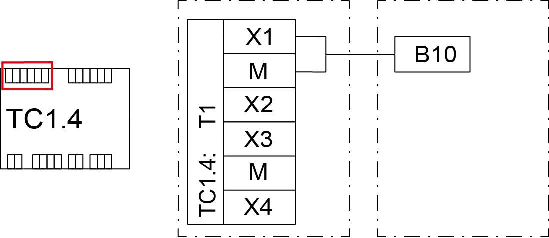
The cascade system supply temperature sensor (B10) is installed in systems with several heat pumps producing heat. The sensor acts as a measurement that controls the cascade system.
Install the sensor in the common supply pipe of the cascade heating system before any additional heat sources. The sensor is an 80 mm water sensor that does not require a separate sensor pocket. The sensor has a 4 m cable with connector. You can extend the sensor in the junction box.