6 Installing the pipes
Pipe installations must be carried out in accordance with the regulations in force. All connections to the heat pump must be made by using approved threaded couplings only.
Taurus heat pumps are not equipped with shut-off valves. These valves must be installed immediately outside the device to facilitate maintenance.
Install a strainer (dirt separator) in the return water pipes of the charge circuit and the collector to prevent any impurities in the network from entering the heat exchanger and causing a blockage in the exchanger. To facilitate the cleaning of the strainer, install a shut-off valve near the strainer.
If the system contains more than one heat pump, or a Gemini heat pump, non-return valves must be installed in the superheating circuit, charge circuit and the collector for each compressor unit. Non-return valves prevent incorrect fluids circulation in the system. For information on how to install non-return valves, please see the connection instructions.
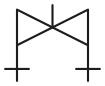
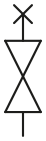
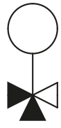
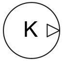
The symbols used in the diagrams are explained in the table below.
| Symbol | Description | Symbol | Description | Symbol | Description |
|---|---|---|---|---|---|
 |
Shut-off valve |
 |
Balancing valve |
 |
Dirt separator |
 |
Vent valve |
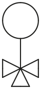 |
Change-over valve |
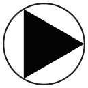 |
Circulator pump |
 |
Non-return valve |
 |
Control valve |
 |
Compressor |
 |
Expansion valve |
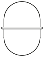 |
Diaphragm expansion tank |
 |
Temperature sensor |
 |
Safety valve |
 |
Heat exchanger |
 |
Pressure gauge |
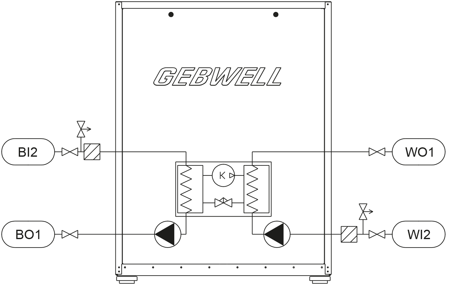
| BO1 | Collector outlet/out | WI2 | Charge circuit return/in |
| BI2 | Collector return/in | ||
| WO1 | Charge circuit supply/out |
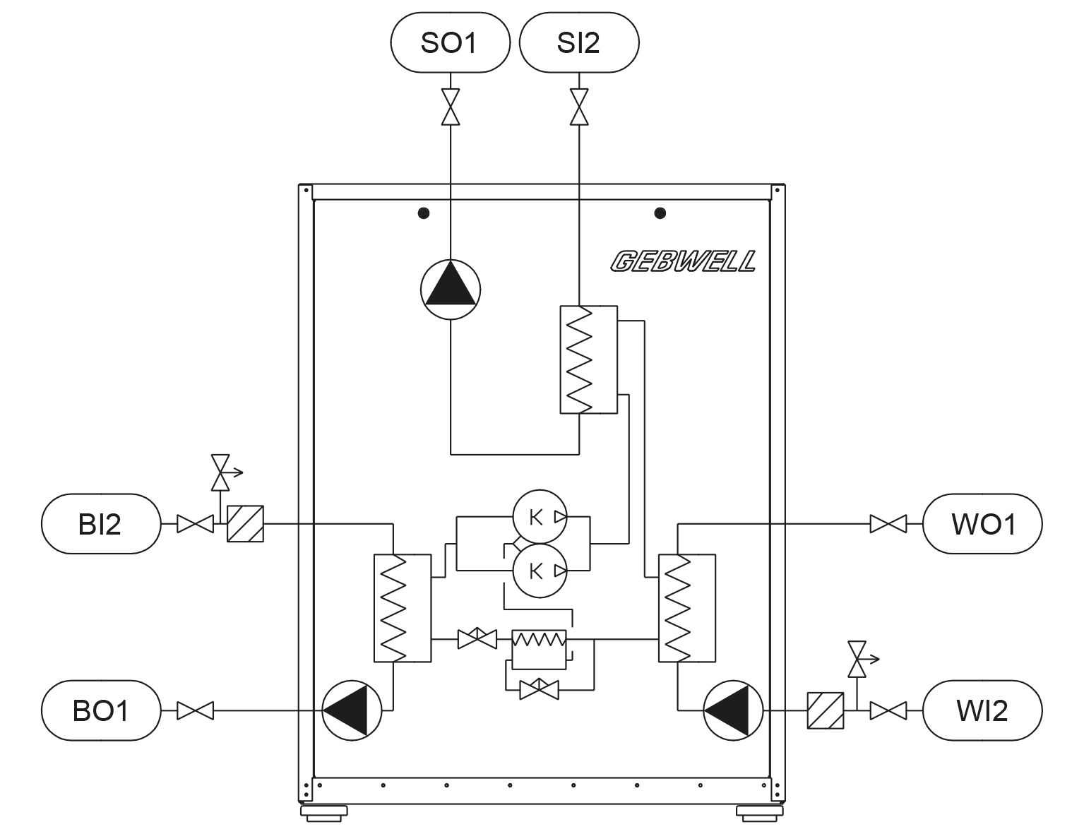
| BO1 | Collector outlet/out | WI2 | Charge circuit return/in |
| BI2 | Collector return/in | SO1 | Superheating circuit supply/out |
| WO1 | Charge circuit supply/out | SI2 | Superheating circuit return/in |