6.3 Brine circuit
- Insulate all of the collector pipes in the building using closed-cell insulation to prevent condensation.
- Only use connecting components designed for cold conditions in the collector.
- Use rubber-insulated brackets for pipes.
- Install shut-off valves in pipe connections as close to the heat pump as possible.
- Enter the type of collecting liquid and the freezing point in the installation record.
- Make sure that the top of the heat pump and the electrical equipment are entirely free of water during operation.
- Only use a diaphragm expansion tank in the collector. The use of a flat expansion tank is not recommended.
- Check the pre-charge pressure of the diaphragm expansion tank in accordance with the plan before pressurising the system. Check the pre-charge pressure when the circuit is open.
- Connect the collector valve group with the related expansion tanks as shown in the figure. The arrow on the poppet seat indicates the flow direction.
- The collector must be pressure-tested with 3 bars of pressure and the test pressure must be sustained for at least 30 minutes.
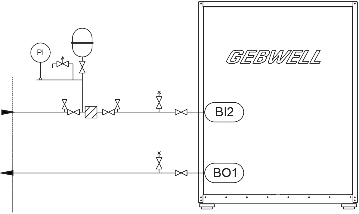
- A: Collector inbound to the heat pump
- B: Collector outbound from the heat pump
- C: Shut-off and control valve
Passive cooling functions best when heat collection is arranged using a bored well. During the summer, loops installed in the soil or in lakes may be at such a high temperature that the required cooling power cannot be obtained. Air within the collector should be allowed to freely rise to the expansion tank. Venting should always take place at the highest point in the collector. If it is necessary to connect the cooling radiator to the highest point in the circuit, venting should take place via the radiator.
Refrigeration can be controlled or regulated using a cooling accessory available for the heat pump. Building automation or ventilation machines can also control the heat pump’s internal source pump. See the electrical diagrams for instructions.