9.3 Heating circuit settings
The heat pump controller is capable of controlling three heating circuits. In menus Heating circuit 1, Heating circuit 2 and Heating circuit 3 you can specify the settings separately for each circuit.
Heating circuit 1 is always the pump heating circuit for which a mixing function cannot be configured. An external circulator pump can be installed into the heating circuit 1 for controller control. Heating circuit 2–3 are optional mixing heating circuits that can be used to adjust a lower temperature. If you use two or three heating circuits, circuit 1 must always have the higher temperature.
HC operating mode indicates the status of the heating circuit.
Sp.room temp. allows you to set two different values for room temperature: Comfort is the basic heating level, and Reduced is the reduced level that is valid during the time control drop period. Actual indicates the valid temperature setting of the heating circuit at the time.
The room temperature sensor must be placed in a central part of the building in order for adjustment to function optimally. If the heating circuit does not include a room temperature sensor, disable the sensor in the service menu. In this case, the controller will use a reference value of 20 °C for heat control.
Room temp. comp. allows you to set how much the room temperature sensor compensation affects the supply water setpoint. The higher the value, the greater the effect. If you set the value to 0, the room temperature sensor acts only as a measuring sensor and does not affect the control of supply water.
Room influence indicates the compensation effect of the room temperature sensor on the supply water temperature. Compensation is affected by the deviation between the setpoint and measured room temperature.
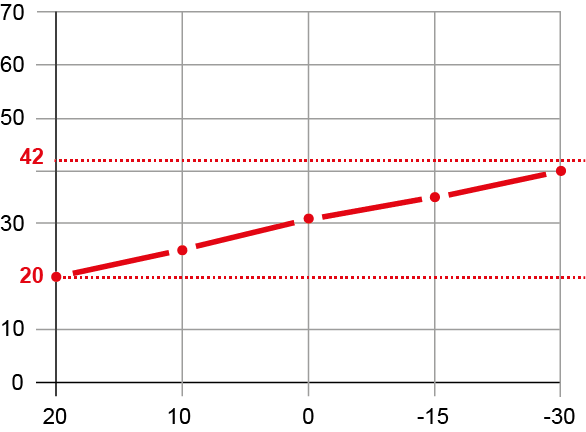
The heating curve is used to calculate the setpoint for the supply water temperature, and this setpoint is used to adjust the supply water temperature according to the prevailing weather conditions. By adjusting the curve, the heating output and room temperature will adapt to you individual needs.
You can change the Y value of the curve at five different outdoor temperature points (20 °C, 10 °C, 0 °C, –15 °C and –30 °C). In the example, the outdoor temperature (°C) is indicated on the X-axis, and the supply water temperature (°C) is indicated on the Y-axis.
For each heating circuit, the upper and lower limit values must be set for supply water. The supply water temperature will remain within these values even if the heating curve exceeds the setpoint.
Example values for underfloor heating and radiator heating are shown in the table. If you use underfloor heating to heat wet rooms, please note the minimum temperature increase when setting the lower limit.
| Form of heating | Upper limit | Lower limit |
|---|---|---|
| Underfloor heating | 40–45 °C | 18–25 °C |
| Radiator heating | 50–80 °C | 15–18 °C |
Present value indicates the supply water temperature.
The Summer-winter switch temperature setting allows you to set the outdoor temperature value at which the heating switches on or off. The factory setting is 16 °C. If the heating is in the Auto mode, switching takes place automatically.
In the weekly calendar, you can set time control for the heating circuits. In time control, the heating circuit changes the mode between the Comfort and Eco modes. Please note that there is a delay in changing temperatures and that time control does not work on all systems.