3 Installing the resistor thermostat housing

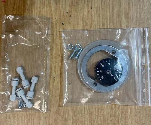
- Open the housing cover and check that all accessories necessary for installation are included.
Figure 1. Thermostat housing installation accessories
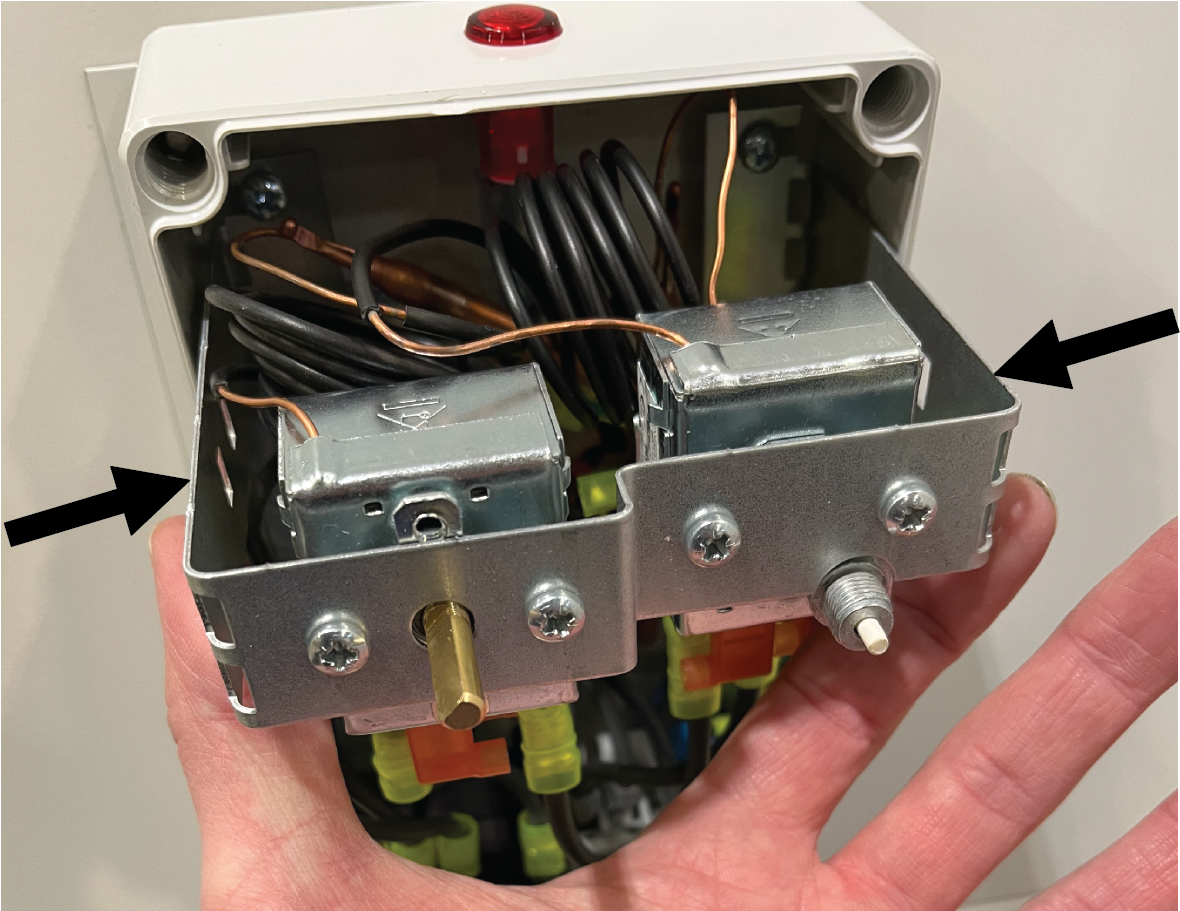
- Remove the bracket containing the thermostat and the overheat protector from the bottom of the housing.
Figure 2. Removing the brackets on the thermostat housing
- Place the sealing ring on top of the resistor flange such that it becomes positioned in between the thermostat housing and the flange.
Figure 3. Installing the sealing ring
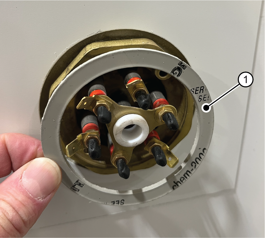
1 Sealing ring - Thread the metal installation ring of the housing over the resistor connectors.
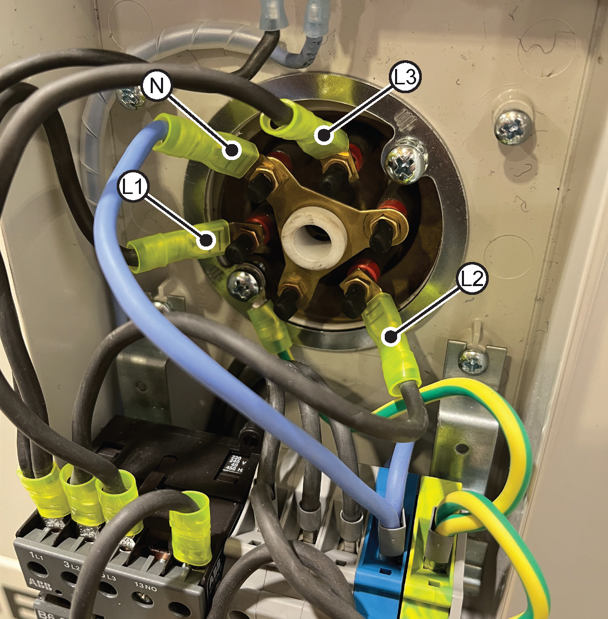
Figure 4. Grounding the thermostat housing
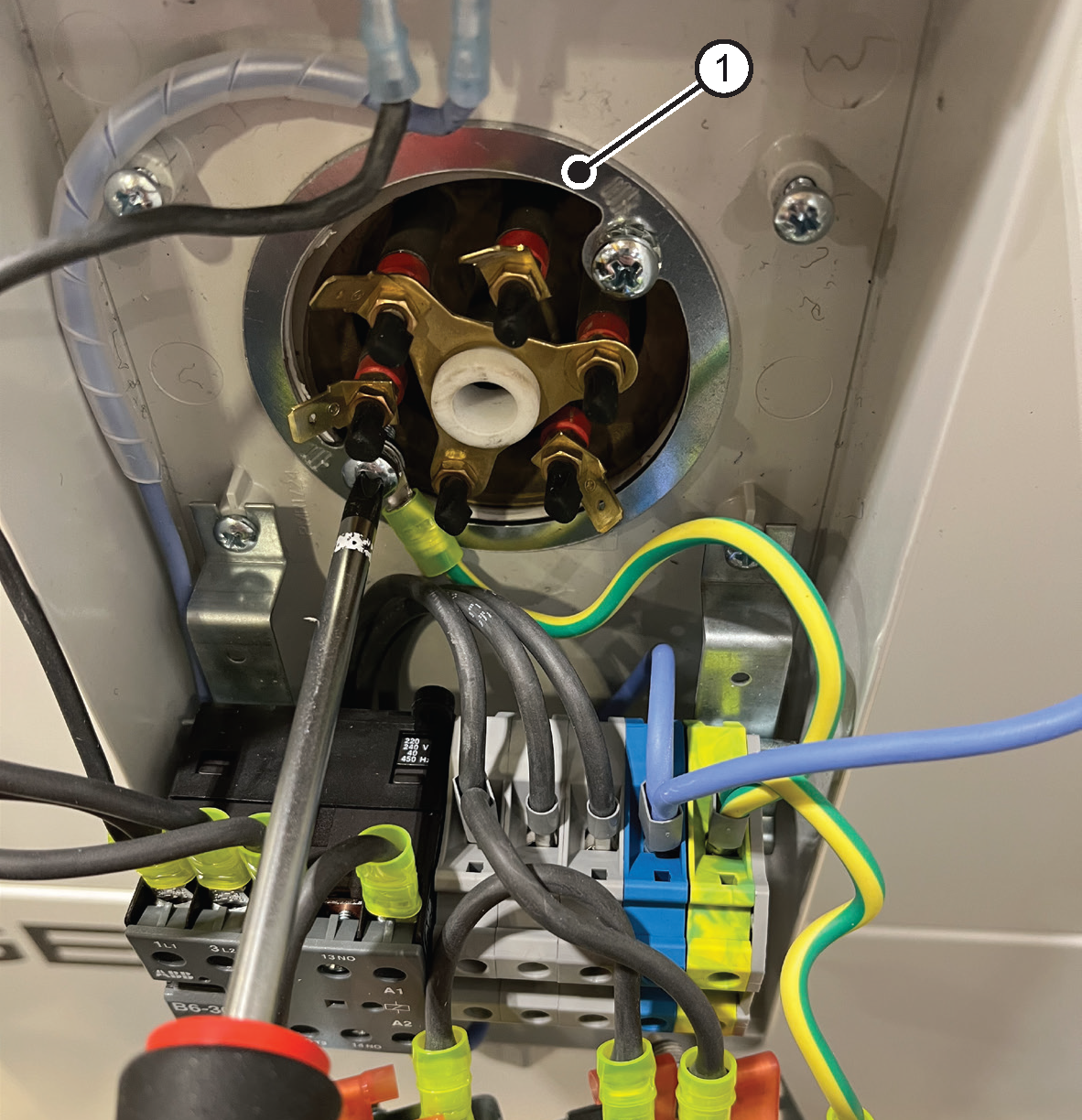
1 Housing mounting ring - Connect the wires coming from the contactor to the electrical terminals L1, L2, L3, and N of the resistor.
Check the tightness of the nut fastening of the resistor spade terminals. If a terminal nut has become loose, tighten the nut only slightly. If force is used when tightening, the electrical connector may break.Figure 5. Connecting the resistor electrical connectors
- Push the capillary sensors of the overheat protector and the thermostat to the middle, into the resistor thermostat pocket.
Insert the overheat protector sensor into the pocket first, to get it to go deeper. Avoid excessive stress of the capillary tubes.Figure 6. Installing the capillary sensors
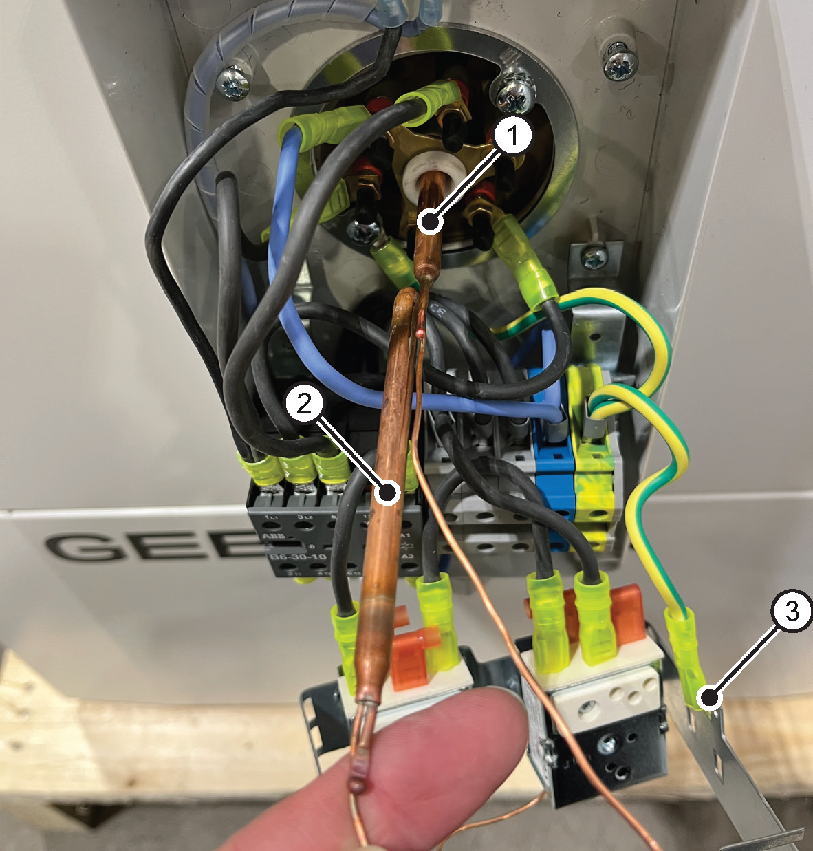
1 Overheat protector capillary sensor 2 Thermostat capillary sensor 3 Ground connector - Slide the bracket containing the thermostat and overheat protector back underneath the fixing screws on the bottom of the housing and tighten the screws.
Make sure all wires are connected.Figure 7. Fixing the brackets
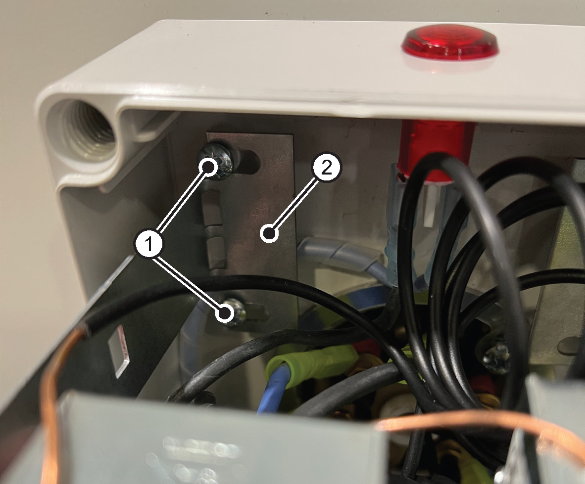
1 Bottom fixing screw 2 Bracket - Install the thermostat control knob in its place.
Figure 8. Thermostat housing control knob
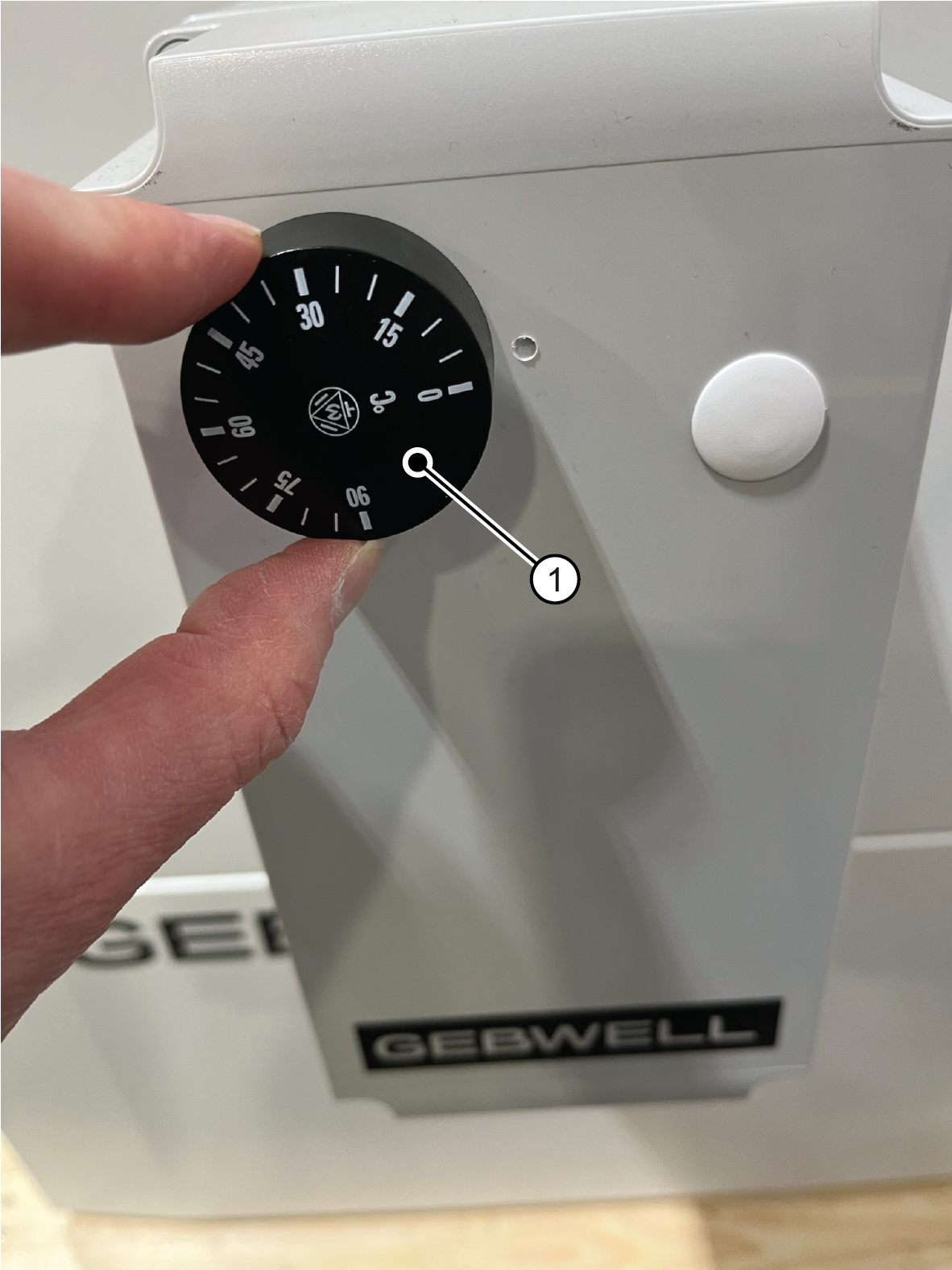
1 Thermostat control knob
What to do next
Take decommissioned products to a WEEE collection point.